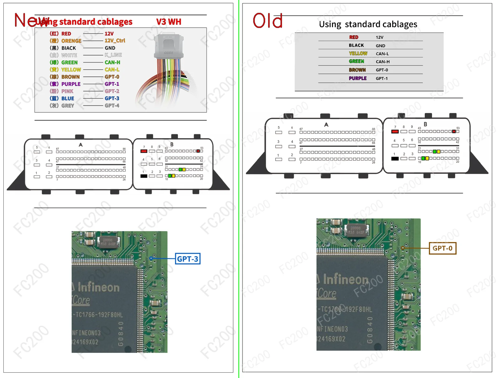
OFFICIAL PINOUT DIAGRAM: BOOT_BOSCH DCU17HD01.png (Boot)1,383,988 bytes
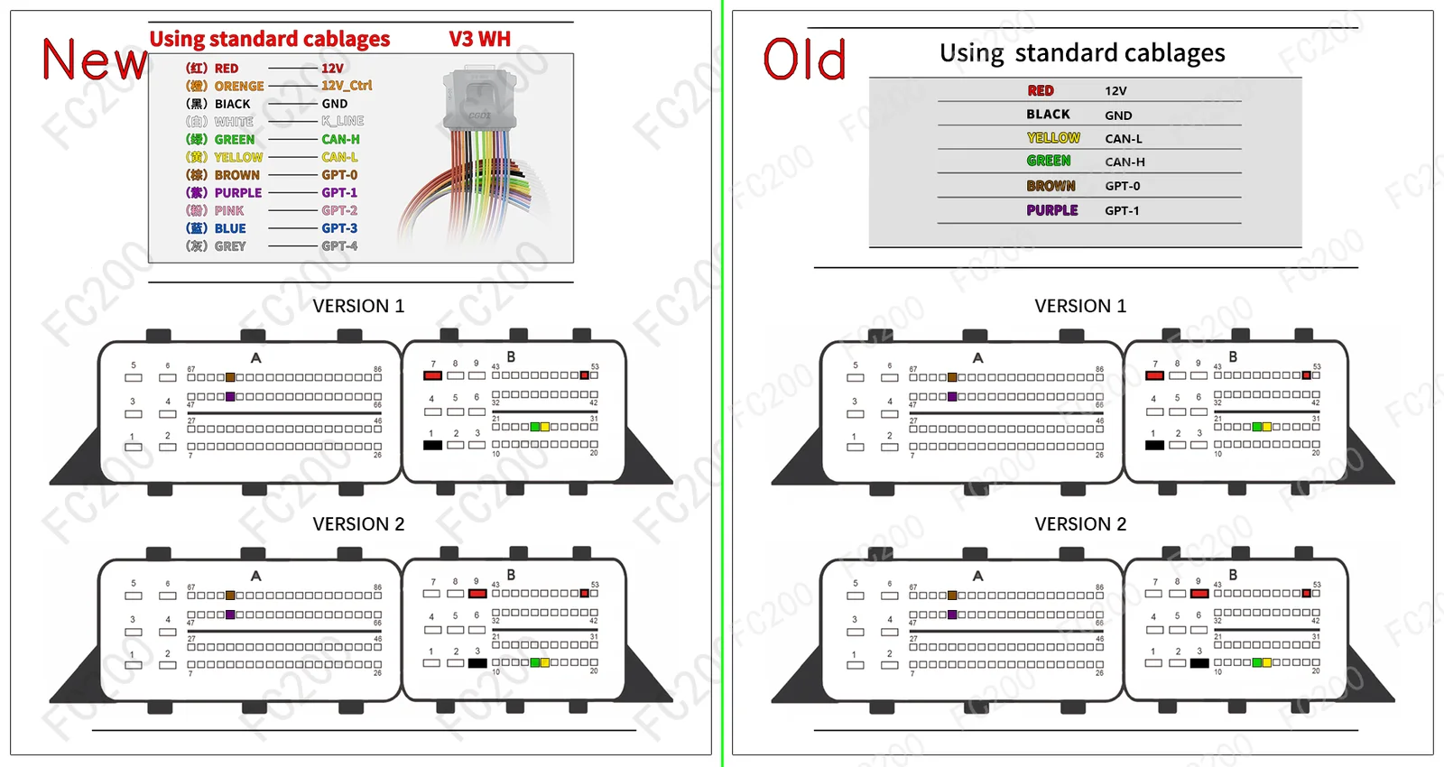
OFFICIAL PINOUT DIAGRAM: BOSCH DCU17HD01.png (Platform / Bench)733,164 bytes
STEP-BY-STEP BENCH CONNECTION PROCEDURE (HOWTO PROTOCOL)BENCH / BOOT
- Step 1 (Terminal 30 & Terminal 15 Power): Apply regulated bench power
13.5V — 13.8Vto constant battery (T30), switched ignition (T15), and ground (GND) pins according to the harness color code above. - Step 2 (CAN Bus & GPT0 / GPT1 Signals): Connect
CAN-H&CAN-L, along with signal leadsGPT0 (S1)&GPT1 (S2)to enter bench service mode without opening the ECU housing. - Step 3 (Full PFLASH + DFLASH Backup Read): Before writing any calibration, read and archive a full backup of internal Program Flash (
PFLASH) and Data Flash / EEPROM (DFLASH).
VEHICLES EQUIPPED WITH ECU DCU17HD01 (11)VEHICLE COMPATIBILITY
VERIFIED FIRMWARE (.BIN) & DAMOS MAPS (.A2L / .KP) FOR DCU17HD01FILE CATALOG
| Format | Engineering File Name | Price / Action |
|---|---|---|
.A2L? .A2L — Automotive ECU Engineering FileVerified binary firmware, WinOLS calibration map pack, or dealer technical schematic for ECU programming and diagnostics. |
P_739_DCU17HD01_8_62_internal_500.a2l | $190 • Open File → |