OEM PINOUT DIAGRAM: CONTINENTAL VGS4-500-NAG2 BENCH_R5F72544R.png (Platform / Bench)634,917 bytes
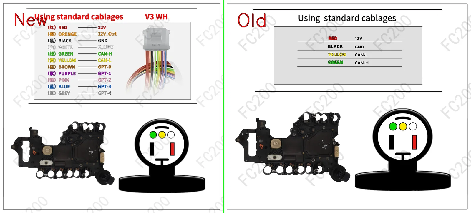
STEP-BY-STEP BENCH CONNECTION PROTOCOL (HOWTO)BENCH / BOOT
- Step 1 (Terminal 30 & Terminal 15 power): Apply stabilized
13.5V — 13.8Vto the permanent power (T30) and ignition (T15) pins, plus ground (GND), following the cable color coding above. - Step 2 (CAN bus & GPT0 / GPT1 generator lines): Connect the
CAN-HandCAN-L, plus the signal wiresGPT0 (S1)andGPT1 (S2)to enter service mode without opening the ECU case. - Step 3 (Full PFLASH + DFLASH backup read): Before any write operation, read and save a full backup of the internal flash (
PFLASH) and the EEPROM area (DFLASH).
VEHICLES FITTED WITH THE VGS4-500-NAG2 ECU (1)FITMENT
| Brand | Model & Engine | ECU & MCU | Open |
|---|---|---|---|
| Universal ECU Protocol | TCU / DSG / CVT Gearbox Control Units (Bench) (Direct bench connector access (Bench / Boot)) | MB_GETRAG_VGS4-500-NAG2 MB_GETRAG_VGS4-500-NAG2 R5F72544R (TriCore) |
Open vehicle → |